WELCOME!

It is hard to believe that it was almost ten years ago I witnessed a CNC router in action for the very first time. I was fascinated and simply had to have one! Although I had been in the creative end of the three dimensional sign business for most of my life I didn't really know what I would do with one of these machines - but I just knew it could do fantastic stuff.

Along with the CNC router I discovered the wonderful material called Precision Board and the glues, primers and other companion products they offer. Since then we have gone through many tons of the material using it in most signs and projects we tackle. This journal will chronicle our many adventures both past, present and future. I'll talk from the perspective of someone who pushes these products to the creative limit on a daily basis. I'll be adding to the stories two or three times each week. -dan

Sunday, September 30, 2012

A little sunshine!


With the house now at lockup stage at long last it is time to get busy in the shop once more. We have plenty of cool projects waiting for us.

One of our projects is for a home prefabricator in Alberta. The preliminary design was hand drawn on my computer using PhotoShop and my digital drawing pad.


Once the design was approved we put measurements to paper and everything was submitted to the local authorities for permits. This seemed to take a long time but eventually we got through that process.


The sign will be built entirely in our shop, loaded onto a truck to move it to the site which is about a thousand miles distant. They will unload it and place it onto steel pilings and then weld it into place.  A sturdy welded steel frame was the first order of business. Everything else will come off of this. If you look at the picture closely you can see the stubby legs with the half inch thick steel plates under them. These will be securely welded to three pilings which will provide the support for the sign and make sure the frost does't move things around.


In the next week or so I'll be welding up the pencil rod sub structure for the sculpted rock work. I'll also be creating the routing files for the sun and the lettering which will be routed from 30lb Precision Board. I'll be using Heico LED lights and surface lighting on this project as well to make it highly visible at night.

Stay tuned...

-dan

Friday, September 28, 2012

First assembly


It's been a while since I had any time to work on the Lucky Jim sign but tonight I squeezed in about half an hour to do a few things and make significant progress. I cut a few pieces on the band saw including the two axles and the frame.  I also cut some axles from 1/4" steel pencil rod and then drilled the holes (slightly off kilter) for the wheels.

The pieces were assembled using five minute epoxy making them plenty strong in a very big hurry. I'll be adding more details with sculpting epoxy the next time I get some time.


I'll be mocking up the box on the mine car next along with Lucky Jim. At that point I can determine the size the sign needs to be and I'll get to sizing the routing files which I've already begun.

Stay tuned for more developments...

-dan

Monday, September 24, 2012

Now they can find us


Yesterday I routed the address marker for the new house. It turned out really nice. The piece will blend perfectly into the other house trim and yet stand out when someone wants to know our house number - not that they won't know it is our house. The truth is there aren't many houses like it around here or anywhere I know of.


In the next few days we'll begin work on the decorative kneesunder the gables. they should be a crative challenge. Stay tuned...

-dan

Wednesday, September 19, 2012

Address marker


Sometimes the files that appear real simple have a lot of steps. Our address sign for the new house was such a piece. It was to be routed from 1.5" 30 lb Precision Board. The address marker would feature the same heart background as the trim.

It started with the vectors - all created in EnRoute Pro. The lettering was a little light for routing so I used the outline tool to add 0.1".  I then deleted the original letters.


I then added a border around the letters. The heart vectors were hand placed in a random pattern.


The outer shape was created as a flat relief 0.7" tall.


I then imported a sandblasted woodgrain bitmap and applied it to the base relief at 0.2"


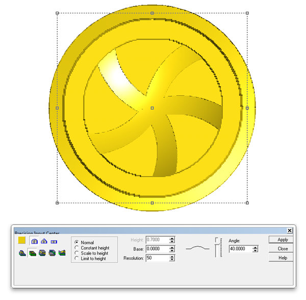
The inner vector was also made into a flat relief 0'4" tall.


The hearts would be raised from the background in three layers. I selected the hearts for the first layer one at a time by picking hearts that did not overlap. They were made into flat reliefs reliefs. By leaving them selected when I did the merge they would be easy to locate and delete when we were done with them.


To do the merge I first selected the outline as the base relief.


Then the heart reliefs were selected one at a time and merged to the base relief. I then deleted them before moving on the the next layer.


These steps were repeated two more times for two more heart layers.


 When the heart layer was complete it looked like this.


I then merged the heart layer to the base layer using the replace command.


The lettering border was next. The reliefs were created as flat reliefs. I merged (highest) these reliefs to the base relief.


The numbers were added to the relief using the bevel tool. The base (straight up portion of the letters) was set at 0.2" high.


The file was now ready for tool pathing and then sent off to the MultiCam. It will be roughed with a 3/8" ball nose bit and then routed using a 1/8" ball nose bit with an 80% overlap.


I'll be showing some pics when this gets to the router in a day or two and then off to the paint department. Stay tuned...

-dan

Tuesday, September 18, 2012

Trim ready for paint


The house project is still going full blast. The outside finishes are almost done, with the windows now being installed. Now it is time to begin putting up the trim - as soon as it is all painted and glazed. To make sure it all lasts for a long time we will apply three base coats of paint to the routed trim and then the three glazes. Today I detailed all the edges and blew off the dust in readiness of the paint. All the vertical pieces are routed. Tomorrow I'll fire up the MultiCam once more to begin routing the horizontal pieces we need.


Tomorrow I'll show how a typical piece of horizontal trim is designed, along with the dressmaker for the front of the house. Stay tuned...

-dan

Tuesday, September 11, 2012

inspiration


I often get asked where I get all my ideas. The answer of course is everything I see and imagine. But a reference library is also critical. I love books. If they are full of pictures and illustrations - so much the better. My wife cringes each time I get near a book store for we know it wont be a cheap exercise but it is critical to gathering ideas. If you look in our financial books there is one category devoted to research and ideas. Books I collect fall into this column. To output creative ideas we must first fill our heads with everything imaginable. It is a job I take seriously.

Picking out books does not take me long. I flip the pages quickly and if three things catch my eye it is a book worth buying. Most likely if there are three good ideas there will be more. When I get home (or in my travels I'll read the book through, storing the images in my head. Then the book is catalogued and placed in the appropriate section for future reference.

Today I head over to Vancouver Island for three days to speak at a tourism conference. The subject I will speak on is signs and how they can create tourism in a BIG way. I'm looking forward to the  trip.

But I am also looking forward to stopping in my travels along the way. There are three bookstores I simply can't drive by and it has been a while since I've visited there. I'm looking forward to adding to my collection.


-dan

Monday, September 10, 2012

Laying down tracks


Today was a busy day but I couldn't resist working just a little on the Lucky Jim Mine sign. The MultiCam was busy routing exterior moldings for the house but as each file finished I snuck in the railroad wheels and tracks on what would have been scrap. I actually ran the wheels twice as the first time they were simply too big for the sign I was building.

I also built the file for the track. It was a quicky.

The vectors were simple. Two parallel rails would form the bent track. The other vector required was the profile of half of a cross section of a train rail. I used the sweep two rails command, and followed the prompts


When it performs the task it shows black until I hit the render button. Meshes show up red. Meshes cannot be tool pathed. We first have to convert them to reliefs.


In order to do this I first created a zero height relief. using my outline vector.


The rail mesh needs to be positioned correctly in the vertical space as I would be adding this volume to the flat, zero height relief. I did this in the front view with the up/down keys.


 Then I selected both the relief and mesh to light up the mesh/relief merge button. In this case I could have used either the add to relief of merge highest.


When I render after merging the mesh and relief it comes out as splotchy red/yellow. I can then move/delete the mesh.


I duplicated the relief and flipped a copy for each rail to create the two halves of the rail. I tool pathed it using a 3/8" ball nose bit with a 90% overlap. This would give me the rounded inside corners I wanted.


I used a five minute epoxy to glue the two halves together.


I used my trusty air-powered die grinder to whip up some railroad ties. This thing is coming together in a hurry... the hard part is done. 


Stay tuned as more parts come together...

-dan

Saturday, September 8, 2012

Mine car wheels

The wheels of the little mine car are a great exercise to practice our building of various shaped reliefs and how to merge them into a final shape which we want. As we build the reliefs we have to keep in mind the final result and then think of what we have to add or take away to get exactly that. There are many ways we could have achieved a similar effect.

We start with the vectors of course - all created inside EnRoute. The wheel will be four inches in diameter (including the flange) and 1" deep.


The back flanges on railway wheels are sloped so the first task was to create a disk using the largest vector circle.  I kept it fairly shallow.


Then I selected the next vector and created a flat disk 0.9" tall. This was then merged with the first tapered disk I created.


Then it was time to knock out the center to make room for the spokes and the hub of the wheel. I created a zero height relief which was then merged to the base relief.


Next up was the spokes. I first created flat reliefs in the shape of the spokes.


The spokes looked good but I wanted them to be curved on top and higher in the center. THis would need to be done in a couple of moved by modifying these reliefs. First ‘I used the done tool to puch down the center in a bowl shape.


Then I used the prism tool to modify the reliefs once more by building them over a cone shape.


These spokes were them merged highest with the base relief.


Next up was the hub of the wheel. I created a flat relief 0.9" tall. This was then merged (replace) with the base relief.


The last step was to add the center section of the hub by adding to the relief.


I then duplicated the wheel to make a set of four. This was tool pathed using a 3/8" ball nose bit for a rough pass at a 50% overlap. A final pass was then added using a 1/8" tapered ball nose bit with an 80% overlap. I'll post some pictures as soon as I put the file on the MultiCam. It will be routed from 1" 30 lb Precision Board.

Stay tuned...

-dan